1. Introduction and Goals
Describes the relevant requirements and the driving forces that software architects and development team must consider.
These include
- underlying business goals, essential features and functional requirements for the system,
- quality goals for the architecture,
- relevant stakeholders and their expectations
fill with content
1.1. Requirements Overview
Contents
Short description of the functional requirements, driving forces, extract (or abstract) of requirements. Link to (hopefully existing) requirements documents (with version number and information where to find it).
Motivation
From the point of view of the end users a system is created or modified to improve support of a business activity and/or improve the quality.
Form
Short textual description, probably in tabular use-case format. If requirements documents exist this overview should refer to these documents.
Keep these excerpts as short as possible. Balance readability of this document with potential redundancy w.r.t to requirements documents.
Examples
insert requirements overview
1.2. Quality Goals
Content
The top three (max five) quality goals for the architecture whose fulfillment is of highest importance to the major stakeholders. We really mean quality goals for the architecture. Don’t confuse them with project goals. They are not necessarily identical.
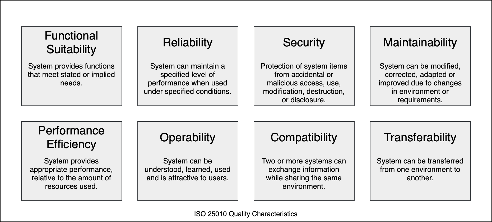
The ISO 25010 standard provides a nice overview of potential topics of interest:
Motivation
You should know the quality goals of your most important stakeholders, since they will influence fundamental architectural decisions. Make sure to be very concrete about these qualities, avoid buzzwords. If you as an architect do not know how the quality of your work will be judged …
Form
A table with the most important quality goals and concrete scenarios, ordered by priorities.
See section 10. Quality Requirements for a complete overview of quality scenarios.
Examples
insert table of quality goals here
1.3. Stakeholder
Content
Explicit overview of stakeholders of the system, i.e. all person, roles or organizations that
- should know the architecture
- have to be convinced of the architecture
- have to work with the architecture or with code
- need the documentation of the architecture for their work
- have to come up with decisions about the system or its development
Motivation
You should know all parties involved in development of the system or affected by the system. Otherwise, you may get nasty surprises later in the development process. These stakeholders determine the extent and the level of detail of your work and its results.
Form
Table with role names, person names, and their expectations with respect to the architecture and its documentation.
complete the stakeholder table:
| Role/Name | Contact | Expectations |
|---|---|---|
| ... | ... | ... |
2. Architecture Constraints
Content
Any requirement that constrains software architects in their freedom of design and implementation decisions or decision about the development process. These constraints sometimes go beyond individual systems and are valid for whole organizations and companies.
Motivation
Architects should know exactly where they are free in their design decisions and where they must adhere to constraints. Constraints must always be dealt with; they may be negotiable, though.
Form
Simple tables of constraints with explanations. If needed you can subdivide them into technical constraints, organizational and political constraints and conventions (e.g. programming or versioning guidelines, documentation or naming conventions)
Examples
insert relevant constraints
3. Context and Scope
Content
System scope and context - as the name suggests - delimits your system (i.e. your scope) from all its communication partners (neighboring systems and users, i.e. the context of your system). It thereby specifies the external interfaces.
If necessary, differentiate the business context (domain specific inputs and outputs) from the technical context (channels, protocols, hardware).
Motivation
The domain interfaces and technical interfaces to communication partners are among your system’s most critical aspects. Make sure that you completely understand them.
Form
- Various context diagrams
- Lists of communication partners and their interfaces.
Examples
See below, separated into business- and technical context.
3.1 Business Context
Content
Specification of all communication partners (users, IT-systems, …) with explanations of domain specific inputs and outputs or interfaces. Optionally you can add domain specific formats or communication protocols.
Motivation
All stakeholders should understand which data are exchanged with the environment of the system.
Form
All kinds of diagrams that show the system as a black box and specify the domain interfaces to communiations partners.
Alternatively (or additionally) you can use a table. The title of the table is the name of your system, the three columns contain the name of the communication partner, the inputs, and the outputs.
Examples
insert diagram or table
(optionally:) insert explanation of external domain interfaces
3.2 Technical Context
Contents
Technical interfaces (channels and transmission media) linking your system to its environment. In addition a mapping of domain specific input/output to the channels, i.e. an explanation with I/O uses which channel.
Motivation
Many stakeholders make architectural decision based on the technical interfaces between the system and its context. Especially infrastructure or hardware designers decide these technical interfaces.
Form
E.g. UML deployment diagram describing channels to neighboring systems, together with a mapping table showing the relationships between channels and input/output.
Examples
insert diagram or table
(optionally:) insert explanation of technical interfaces
insert mapping of input/output to channels
4. Solution Strategy
Contents
A short summary and explanation of the fundamental decisions and solution strategies, that shape the system’s architecture. These include
- technology decisions
- decisions about the top-level decomposition of the system, e.g. usage of an architectural pattern or design pattern
- decisions on how to achieve key quality goals
- relevant organizational decisions, e.g. selecting a development process or delegating certain tasks to third parties.
Motivation
These decisions form the cornerstones for your architecture. They are the basis for many other detailed decisions or implementation rules.
Form
Keep the explanation of these key decisions short.
Motivate what you have decided and why you decided that way, based upon your problem statement, the quality goals and key constraints. Refer to details in the following sections.
You might use a list of solution-approaches or a table similar to the following:
Quality goal Scenario Solution approach Link to Details <Q-goal 1> <Text> <Text> <Link> <Q-goal 2> <Text> <Text> <Link> Examples
insert solution strategy
list or table
5. Building Block View
Content
The building block view shows the static decomposition of the system into building blocks (modules, components, subsystems, classes, interfaces, packages, libraries, frameworks, layers, partitions, tiers, functions, macros, operations, data structures, …) as well as their dependencies (relationships, associations, …)
This view is mandatory for every architecture documentation. In analogy to a house this is the floor plan.
Motivation
Maintain an overview of your source code by making its structure understandable through abstraction.
This allows you to communicate with your stakeholder on an abstract level without disclosing implementation details.
Form
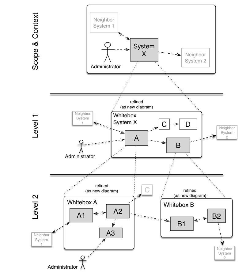
The building block view is a hierarchial collection of black boxes and white boxes (see figure below) and their descriptions.
- Level 1 is the white box description of the overall system together with black box descriptions of all contained building blocks.
- Level 2 zooms into some building blocks of level 1. Thus it contains the white box description of selected building blocks of level 1, together with black box descriptions of their internal building blocks.
- Level 3 zooms into selected building blocks of level 2, and so on.
Examples
5.1. Whitebox Overall System
Here you describe the decomposition of the overall system using the following white box template. It contains
- an overview diagram
- a motivation for the decomposition
- black box descriptions of the contained building blocks. For these we offer you alternatives:
- use one table for a short and pragmatic overview of all contained building blocks and their interfaces
- use a list of black box descriptions of the building blocks according to the black box template (see below). Depending on your choice of tool this list could be sub-chapters (in text files), sub-pages (in a Wiki) or nested elements (in a modelling tool).
- (optional:) important interfaces, that are not explained in the black box templates of a building block, but are very important for understanding the white box.
Since there are so many ways to specify interfaces why do not provide a specific template for them.
In the best case you will get away with examples or simple signatures.
insert overview diagram of overall system
describe motivation/reasoning for overall system decomposition
describe contained building blocks (blackboxes)
(optionally) describe important interfaces
Insert your explanations of black boxes from level 1:
If you use tabular form you will only describe your black boxes with name and responsibility according to the following schema:
Name Responsibility <black box 1> <Text> <black box 2> <Text> If you use a list of black box decriptions then you fill in a separate black box template for every important building block . Its headline is the name of the black box.
Name black box 1
Here you describe <black box 1> according the the following black box template:
- Purpose/Responsibility
- Interface(s), when they are not extracted as separate paragraphs. This interfaces may include qualities and performance characteristics.
- (Optional) Quality-/Performance characteristics of the black box, e.g.availability, run time behavior, ….
- (Optional) directory/file location
- (Optional) Fulfilled requirements (if you need traceability to requirements).
- (Optional) Open issues/problems/risks
You can use a table or text.
Purpose/Responsibility
Interface(s)
(Optional) Quality/Performance Characteristics
(Optional) Directory/File Location
(Optional) Fulfilled Requirements
(optional) Open Issues/Problems/Risks
Name black box 2
black box template
Name black box n
black box template
Name interface 1
...
Name interface n
5.2. Level 2
Here you can specify the inner structure of (some) building blocks from level 1 as white boxes.
You have to decide which building blocks of your system are important enough to justify such a detailed description. Please prefer relevance over completeness. Specify important, surprising, risky, compelx or volatile building blocks. Leave out normal, simple, boring or standardized parts of your system
5.2.1. White Box <building block 1>
Specifies the internal structure of _building
Use the white box template (see above).
insert white box template of building block 1
5.2.2 White Box <building block 2>
insert white box template for building block 2
5.3. Level 3
Here you can specify the inner structure of (some) building blocks from level 2 as white boxes.
When you need more detailed levels of your architecture please copy this part of arc42 for additional levels.
5.3.1 Whitebox <Building Block 1>
insert
5.3.2. Whitebox <Building Block 2>
insert
6. Runtime View
Content
The runtime view describes concrete behavior and interactions of the system’s building blocks in form of scenarios from the following areas:
- important use cases or features: how do building blocks execute them?
- interactions at critical external interfaces: how do building blocks cooperate with users and neighbouring systems?
- operation and administration: launch, start-up, stop
- error and exception scenarios
Remark: The main criterion for the choice of possible scenarios (sequences, workflows) is their architectural relevancy. It is not important to describe a large number of scenarios. You should rather document a representative selection.
Motivation
You should understand how (instances of) building blocks of your system perform their job and communicate at runtime. You will mainly capture scenarios in your documentation to communicate your architecture to stakeholders that are less willing or able to read and understand the static models (building block view, deployment view).
Form
There are many notations for describing scenarios, e.g.
- numbered list of steps (in natural language)
- activity diagrams or flow charts
- sequence diagrams
- BPMN or EPCs (event process chains)
- state machines
- …
Examples
6.1. <Runtime Scenario 1>
insert runtime diagram or textual description of the scenario
insert description of the notable aspects of the interactions between the building block instances depicted in this diagram.
6.2. <Runtime Scenario 2>
insert runtime diagram or textual description of the scenario
insert description of the notable aspects of the interactions between the building block instances depicted in this diagram.
7. Deployment View
Content
The deployment view describes:
- the technical infrastructure used to execute your system, with infrastructure elements like geographical locations, environments, computers, processors, channels and net topologies as well as other infrastructure elements and
- the mapping of (software) building blocks to that infrastructure elements.
Often systems are executed in different environments, e.g. development environment, test environment, production environment. In such cases you should document all relevant environments.
Especially document the deployment view when your software is executed as distributed system with more then one computer, processor, server or container or when you design and construct your own hardware processors and chips.
From a software perspective it is sufficient to capture those elements of the infrastructure that are needed to show the deployment of your building blocks. Hardware architects can go beyond that and describe the infrastructure to any level of detail they need to capture.
Motivation
Software does not run without hardware. This underlying infrastructure can and will influence your system and/or some cross-cutting concepts. Therefore, you need to know the infrastructure.
Form
Maybe the highest level deployment diagram is already contained in section 3.2. as technical context with your own infrastructure as ONE black box. In this section you will zoom into this black box using additional deployment diagrams.
- UML offers deployment diagrams to express that view. Use it, probably with nested diagrams, when your infrastructure is more complex.
- When your (hardware) stakeholders prefer other kinds of diagrams rather than UML deployment diagram, let them use any kind that is able to show nodes and channels of the infrastructure.
Examples
7.1. Infrastructure Level 1
Describe (usually in a combination of diagrams, tables, and text):
- the distribution of your system to multiple locations, environments, computers, processors, .. as well as the physical connections between them
- important justification or motivation for this deployment structure
- Quality and/or performance features of the infrastructure
- the mapping of software artifacts (building blocks) to elements of the infrastructure
For multiple environments or alternative deployments please copy that section of arc42 for all relevant environments.
insert infrastructure overview diagram
Motivation
insert description of motivation or explanation in text form
(optional) Quality and/or Performance Features
optionally insert description quality or performance features
Mapping
insert description of mapping of building blocks
Infrastructure Level 2
Here you can include the internal structure of (some) infrastructure elements from infrastructure level 1.
Please copy the structure from level 1 for each selected element.
Crosscutting Concepts
Content
This section describes overall, principal regulations and solution ideas that are relevant in multiple parts (→ cross-cutting) of your system. Such concepts are often related to multiple building blocks. They include many different topics, such as
- domain models
- architectur patterns or design patterns
- rules for using specific technology
- principale, often technical decisions of overall decisions
- implementation rules
Motivation
Concepts form the basis for conceptual integrity (consistency, homogeneity) of the architecture. Thus, they are an important contribution to achieve inner qualities of your system.
Some of these concepts cannot be assigned to individual building blocks (e.g. security or safety). This is the place in the template that we provided for a cohesive specification of such concepts.
Form
The form can be varied:
- concept papers with any kind of structure
- cross-cutting model excerpts or scenarios using notations of the architecture views
- example implementations,especially for technical concepts
- reference to typical usage of standard frameworks (e.g. using Hibernate for object/relational mapping)
Structure of this Section
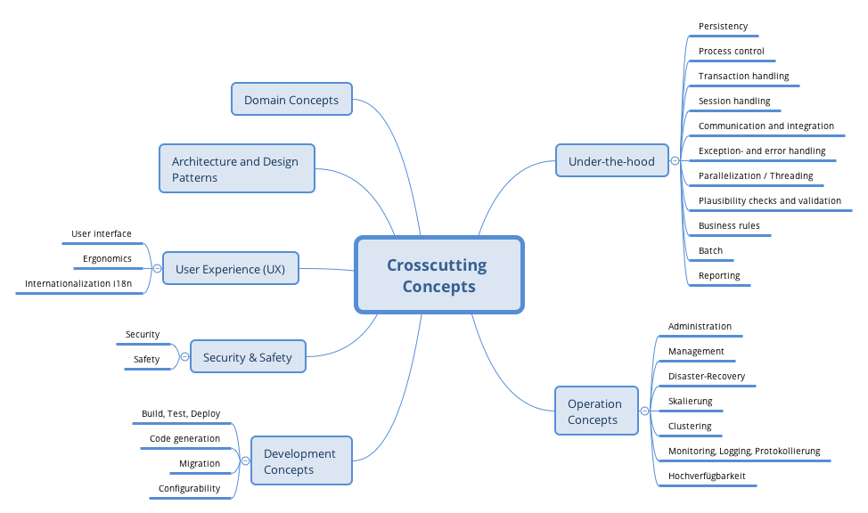
A potential (but not mandatory) structure for this section could be:
- Domain concepts
- User Experience concepts (UX)
- Safety and security concepts
- Architecture and design patterns
- “Under-the-hood” concepts
- Development concepts
- Operational concepts
Note: it might be difficult to assign individual concepts to one specific topic on this list.
Background
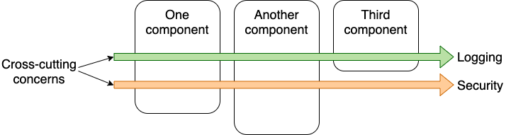
Some topics within systems often concern multiple building blocks, components or elements. It might be easier to communicate or document such cross-cutting topics at a central location, instead of repeating them in the description of the concerned elements.
Certain concepts might concern all elements of a system, others might only be relevant for a few. In the diagram below, logging concerns all three components, whereas security is relevant only for two components.
Some real-life examples:
- Within a system, a common format for log-messages shall be established, combined with a common convention of chosing the appropriate log-destination. These decisions, along with implementation examples, could be described as “logging-concept”.
- A system has numerous backend services, that communicate among each other based upon remote procedure calls or http-based REST. Calling services (“consumers”) always need to authenticate themselves to the called service (“provider”). For this authentication, a central common authorization service has to be used. The technical and organizational details such authentication could be described as “backend authentication concept”.
- (taken from the HTML Sanity Checker, see below): All (7+) checker components within the system are structured according to the strategy pattern.
Examples
describe concepts here
9. Architecture Decisions
Content
Important, expensive, large scale or risky architecture decisions including rationales. With “decisions” we mean selecting one alternative based on given criteria.
Please use your judgement to decide whether an architectural decision should be documented here in this central section or whether you better document it locally (e.g. within the white box template of one building block). Avoid redundant texts. Refer to section 4, where you captured the most important decisions of your architecture already.
Motivation
Stakeholders of your system should be able to comprehend and retrace your decisions.
Form
- ADR (architecture decision record) for every important decision
- list or table, ordered by importance and consequences or
- more detailed in form of separate sections per decision
Background (on ADRs)
Smaller pieces of documentation are easier to read, create and maintain. When it comes to architecture decisions, development teams will often:
- know about the decision, as it visible e.g. in source code, but
- miss the motivation behind that decision (see Nygard 2011)
Therefore you should document a few important decisions together with their motivation, reasoning
Our proposal concerning decisions
Keep a collection of architecturally significant decisions, those decisions that affect the structure, quality characteristics, important (especially external) dependencies and interfaces, or construction techniques (thanx to Michael Nygard for this proposal)
You might follow the Nygard-structure, which works as follows:
Section Description Title Decisions should have a proper name. For example, “ADR 42: Strategy-Pattern for multiple checking algorithms” or “ADR 9: Keycloak for secrets management” Context Describe the situation, including technical, political, social, and project aspects. These forces might be in tension. Decision What is our decision (reply to the forces described in the context) Status A decision may be “proposed” if the important stakeholders haven’t agreed with it yet, or “accepted” once it is agreed. It could also be “deprecated” or “superseded”, hopefully with a reference to its replacement. Consequences What will or can happen as consequences of this decision. All consequences should be listed here, not just the “positive” ones. A particular decision may have positive, negative, and neutral consequences, but all > of them affect the team and project in the future. You can find additional structures of ADR in the ADR Github collection
Examples
describe important architecture decisions here
10. Quality Requirements
Content
This section contains all quality requirements as quality tree with scenarios. The most important ones have already been described in section 1.2. Quality Goals.
Here you can also capture quality requirements with lesser priority, which will not create high risks when they are not fully achieved.
Motivation
Since quality requirements will have a lot of influence on architectural decisions you should know for every stakeholder what is really important to them, concrete and measurable.
Examples
10.1. Quality Requirements
Content
The table or tree (as defined in ATAM – Architecture Tradeoff Analysis Method) of quality requirements, with quality/evaluation scenarios as leaves.
Motivation
The table or tree structure with priorities provides an overview for a sometimes large number of quality requirements.
Form
The quality tree is a high-level overview of the quality goals and requirements:
- a table, containing specific quality requirements
- tree-like refinement of the term “quality”. Use “quality” or “usefulness” as a root
- a mind map with quality categories as main branches
In any case the tree should include links to the scenarios of the following section.
describe quality tree here
10.2. Quality Scenarios
Content
Concretization of (sometimes vague or implicit) quality requirements using (quality) scenarios.
These scenarios describe what should happen when a stimulus arrives at the system.
For architects, two kinds of scenarios are important:
- Usage scenarios (also called application scenarios or use case scenarios) describe the system’s runtime reaction to a certain stimulus. This also includes scenarios that describe the system’s efficiency or performance. Example: The system reacts to a user’s request within one second.
- Change scenarios describe a modification of the system or of its immediate environment. Example: Additional functionality is implemented or requirements for a quality attribute change.
Motivation
Scenarios make quality requirements concrete and allow to more easily measure or decide whether they are fulfilled.
Especially when you want to assess your architecture using methods like ATAM you need to describe your quality goals (from section 1.2) more precisely down to a level of scenarios that can be discussed and evaluated.
Form
Tabular or free form text.
describe quality scenarios here
11. Risks and Technical Dept
Content
A list of identified technical risks or technical debts, ordered by priority
Motivation
“Risk management is project management for grown-ups” (Tim Lister, Atlantic Systems Guild.)
This should be your motto for systematic detection and evaluation of risks and technical debts in the architecture, which will be needed by management stakeholders (e.g. project managers, product owners) as part of the overall risk analysis and measurement planning.
Form
List of risks and/or technical debts, probably including suggested measures to minimize, mitigate or avoid risks or reduce technical debts.
Examples
insert list or table of known problems, risks or technical debt
12. Glossary
Content
The most important domain and technical terms that your stakeholders use when discussing the system.
You can also see the glossary as source for translations if you work in a multi-language environment (i.e. in offshore development models).
Motivation
You should clearly define your terms, so that all stakeholders
- have an identical understanding of these terms
- do not use synonyms and homonyms
Form
- A simple table with columns <Term> and <Definition>
- Potentially more columns for translations
Term Definition <Term-1> <definition-1> <Term-2> <definition-2> Examples
insert glossary (and optionally translation) table